Updated 2005-01-21 : Added some pictures
First version 2005-01-19
Warning this modification could shorten the lif of your dreamcast.
I tried to set my dreamcast up to be able to read cdrw using some tutorials on the Internet, but it wouldn't work, in fact the 450 ohms resistor I used was too low (300 Ohms in parallel), I hooked up a trimmer in parallel with the optical unit's trimmer and made some tests (the values I give are for parallel resistors) :
530 ohms : CDR works CDRW does not
507 ohms : CDR works CDRW does not
475 ohms : CDR seems to start having trouble reading CDRW works !
430 ohms : CDR makes ugly sounds CDRW works
395 ohms : CDR more noise still works CDRW works
342 ohms : CDR does not work CDRW works
320 ohms : neither work.
I tried two different brands of CDRW, both worked (but I made all the tests with only one). I had to use a boot disc, autoselfboot CDRW never worked.
So I must use a resistor in between 475 and 342 ohms, that's for parallel value, as the optical unit's trimmer is set to about 900ohms it gives me 1005ohms and 550ohms for extreme limits.
If you want to try by yourself make some experimentations with a 10K trimmer.
Warning it may be dangerous for the laser diode to use values too low, don't go under 200 ohms in parallel.
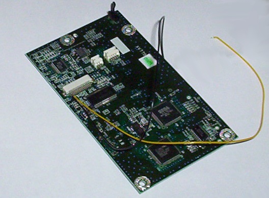
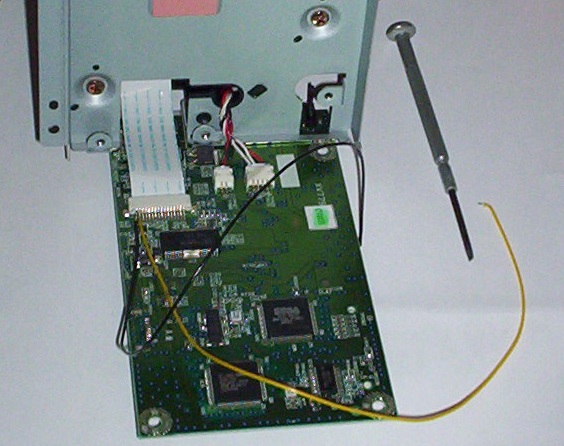
Here's how I soldered my wires :
First you'll have to open your dreamcast, I assume you're able to do so (and you can solder without messing the components around).
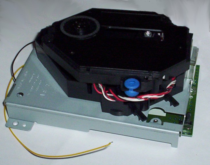
Remove the optical unit, only 3 screws and here you go.
Open the optical unit, there's 5 screws, two of them are hidden under the black pad (where I put red dots on the image below) if you manage to make the solders without disconnecting the wires, fine, because they're hard to reconnect.
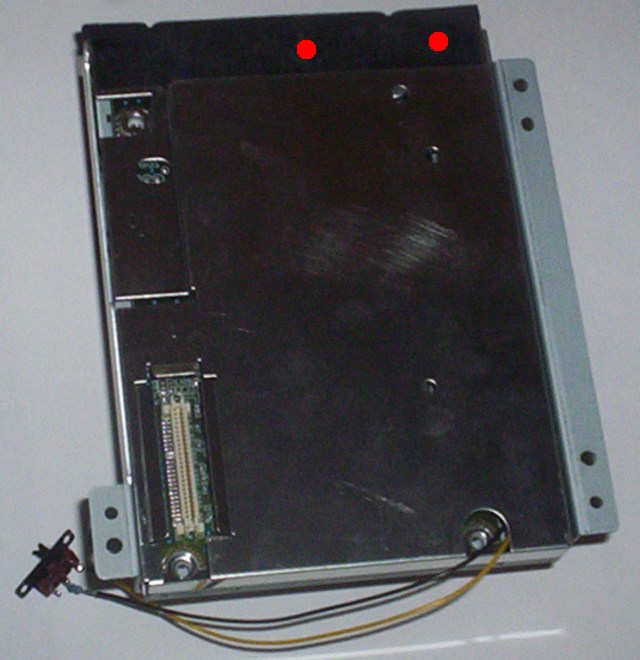
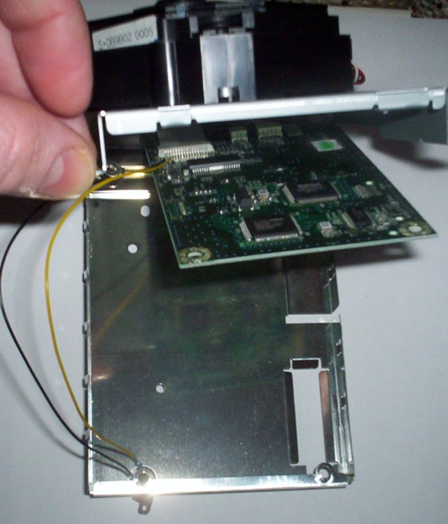
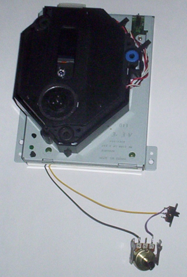
You have to solder two wires to the two leftmost pins of the ribbon cable connector (in fact those two pins lead directly to the two pins of the optical unit trimmer on which other cdrw tutorials said to solder wires)
Beware not to melt the ribbon if soldering like this.
A good place for the wires through the shield is the hole for the screw (see picture 1 too)
Then close the optical unit
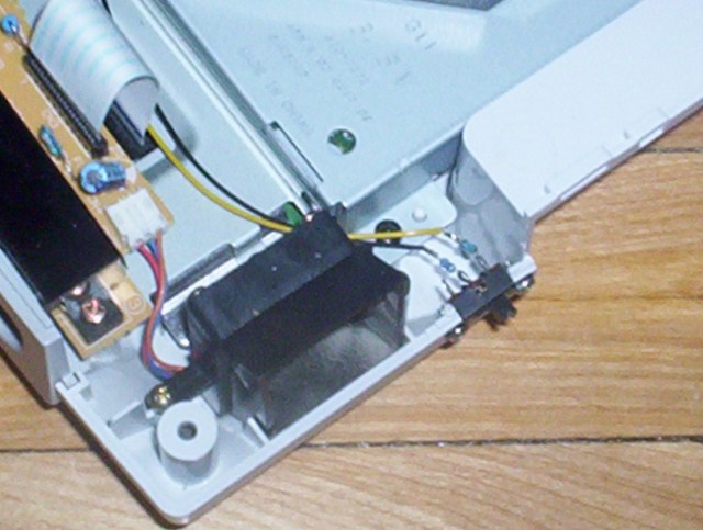
Solder a resistor (or a trimmer for testing) and a switch at the end of the wires
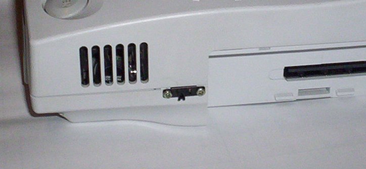
Make a hole in the dreamcast body and here you are.
Of course I don't take responsability if you burn anything trying to follow this tutorial, this come with hope that it can be useful, but without any warranty.